This post is also available in:  Suomi
Suomi Deutsch
 polski
The new welding procedure test standard, EN-ISO 15614-1:2017, provides recommendations for the measurement and calculation of heat input. In concrete terms, what does this mean for MIG/MAG welding? And how can workshops carry out these calculations in practice?
Understanding the new welding procedure test standard
Section 8.4.7 of the EN-ISO 15614-1:2017 standard, titled “Heat input (arc energy)”, states the following for the new welding test procedure:
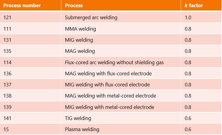
“Users can use either heat input or arc energy (J/mm). Arc energy must be calculated in accordance with ISO/TR 18491. The k factor pursuant to ISO/TR 17671‑1 must be taken into account in the calculation of heat input. The calculation (of either heat input or arc energy) must be documented.”
“Arc energy and heat input both indicate the heat that arises as a result of the welding arc. In the past, these were regarded as alternative terms for the same quantity, but they are now calculated via different formulae. Users can use heat input or arc energy in the monitoring of welds, to be calculated in accordance with ISO/TR 18491.”
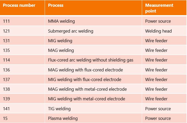
The new welding procedure test standard refers to the technical reports for ISO/TR 18491 and 17671-1, which state that arc voltage must be measured as close to the arc as possible. This way, voltage losses caused by welding cables can be eliminated. Table 1 presents the recommended measurement points for various welding processes.
Formulae for calculating arc energy
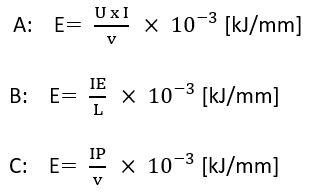
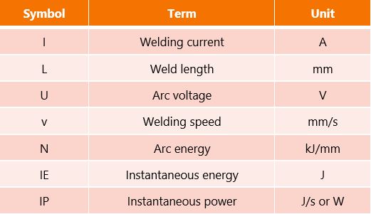
Pursuant to the ISO/TR 18491 report, formulae A, B, and C are used to calculate arc energy. The terms applied are presented in Table 2.
How are the formulae applied?
Formulae A, B, and C are suitable for non-waveform-controlled welding methods. Only formulae B and C may be used for calculations related to waveform-controlled welding methods. Instantaneous energy or power must be measured with an external meter if the welding machine does not display it. In both cases, the sampling frequency must be no less than 10 times the waveform frequency.
ISO/TR 18491 defines waveform-controlled welding thus:
“Welding process modification of the voltage and/or current wave shape to control characteristics such as droplet shape, penetration, wetting, bead shape, or transfer mode(s).”
The heat input calculation formula
The ISO/TR 17671-1 standard presents the thermal efficiencies of various welding processes and a formula for calculating heat input:
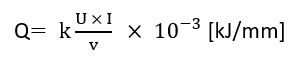
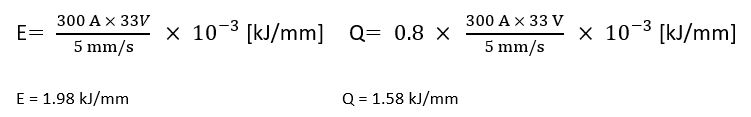
To determine heat input, we must first calculate the arc energy and multiply it by the thermal efficiency. Below, we provide an example of the calculation of arc energy (E) and heat input (Q) in MIG/MAG welding. Such calculations that use averages for the current and the voltage are applicable only for non-waveform-controlled welding:
High welding currents and thin welding cables lead to voltage losses
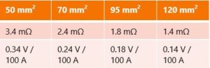
Arc voltage must be measured as close to the arc as possible, to eliminate voltage losses caused by welding cables. In practice, what are the factors that influence voltage losses?
Example:
- 30-meter, 70 mm2 interconnection cable
- 30-meter, 70 mm2 ground cable
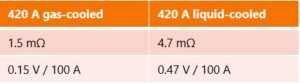
- 420 A, 4.5-meter liquid-cooled welding torch
The welding parameters from the power source are 500 A and 39 V (19.5 kW). Voltage loss is 9.55 V, and power loss is 4.8 kW. This shows that the voltage losses are at their greatest when long and thin welding cables and high welding currents are used.
Performing practical welding tests to measure the effective and calculated power
Let’s revisit the heat input calculation method presented in ISO/TR 18491. Method A, which uses averages for the welding current (I) and the arc voltage (U), is suitable for non-waveform-controlled welding. In contrast, methods B and C measure instantaneous energy (IE) or power (IP), which is required for the calculations for waveform-controlled welding. These methods can be used also for non-waveform-controlled welding processes.
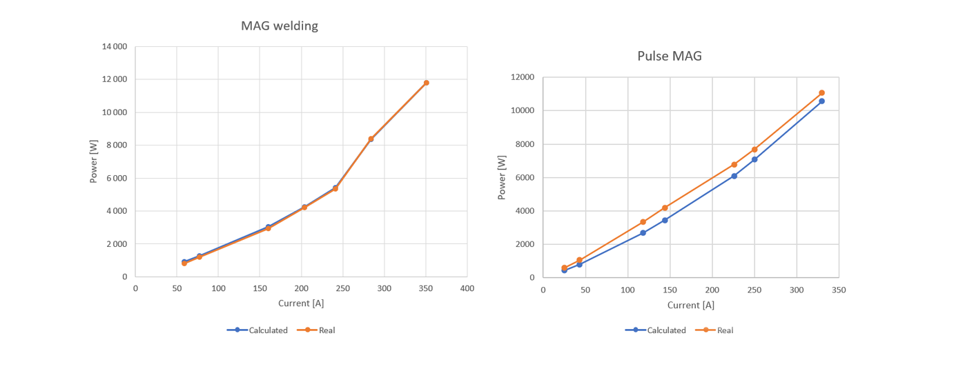
The definition of waveform-controlled welding is not clear-cut, and that may give rise to differing interpretations. Because of this, we carried out practical welding tests to measure the effective and calculated power (averages were used for the current and the voltage in these calculations).
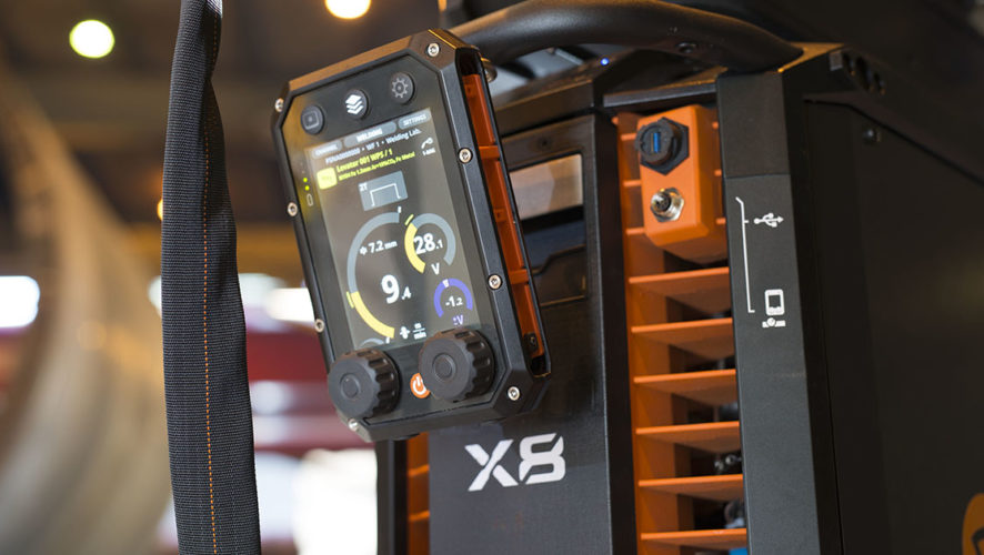
The welding tests were performed with Kemppi’s X8 MIG Welder welding machine, ER70S-6 Ø 1.2 mm solid wire, and Ar + 18% CO2 mixed gas. Welding was carried out in the form of standard and pulsed-MAG welding in various power ranges.
Table 6 presents the results from the MAG welding tests, which show an error value of 12.8% at the lowest measured value (59 A). As the power is increased, the error decreases, and it is no longer significant at currents exceeding 200 A.
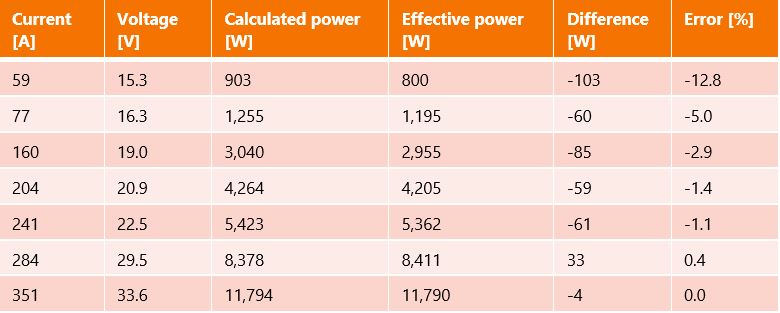
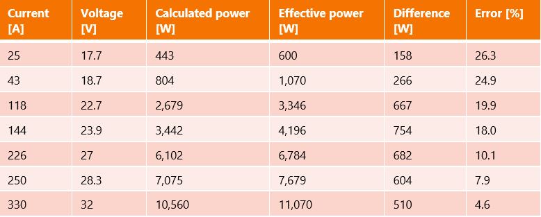
Table 7 presents results from pulsed MAG welding tests which demonstrate that error is present across the entire power range. The relative error is at its greatest at low power.
How new MIG/MAG machines make heat input calculations easier
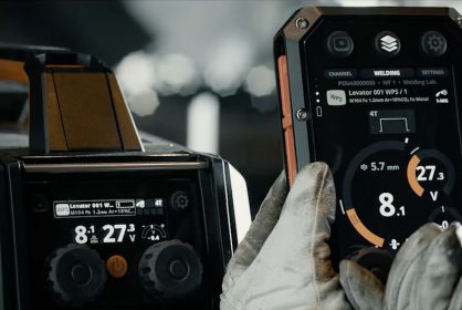
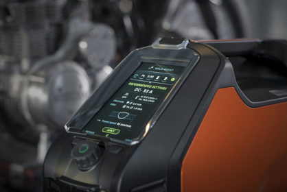
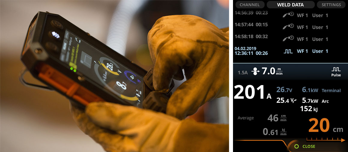
Calculating heat input does not have to be difficult; Kemppi’s latest MIG/MAG welding machine makes such calculations easier. The X8 MIG Welder measures arc voltage directly at the contact tip, to eliminate voltage losses. It calculates instantaneous power as per the standards and has a sampling frequency of up to 20,000 Hz. The device can also determine the welding speed when the welder indicates the weld length upon completion of the weld. After this, the machine automatically displays the effective heat input.
This feature makes jobs such as filling in Welding Procedure Qualification Records easier since the required information on welding parameters, welding speed, and heat input is automatically generated by the X8 Control Pad unit after welding.
So what is the take-home message here? From the perspective of heat input calculations, voltage measurements should be carried out as close to the arc as possible because of voltage losses caused by welding cables. At least in pulsed-MAG welding, the effective power should be used in the calculations, because some level of error occurs across the whole power range.
However, performing calculations with pen and paper is a thing of the past, because the latest MIG/MAG machines make life a little bit easier for welding engineers, offering accurate automated calculation of heat input.
Discover the X8 MIG Welder.